Best Practices for Gear Pump Installation and Alignment
Proper gear pump installation and alignment are essential for stable flow, efficient performance, reduced wear, and long service life.
Whether a gear pump is used in hydraulic systems, oil transfer, chemical processing, lubrication circuits, or general industrial fluid handling,
correct setup directly affects reliability, noise level, energy use, maintenance frequency, and overall operating cost.
This guide provides industry-standard, SEO-friendly, and practical information on gear pump installation best practices, alignment methods,
recommended checks, common mistakes, troubleshooting points, and technical specifications. It is written for blog pages, category pages,
product support pages, industrial knowledge bases, and commercial website content.
What Is a Gear Pump?
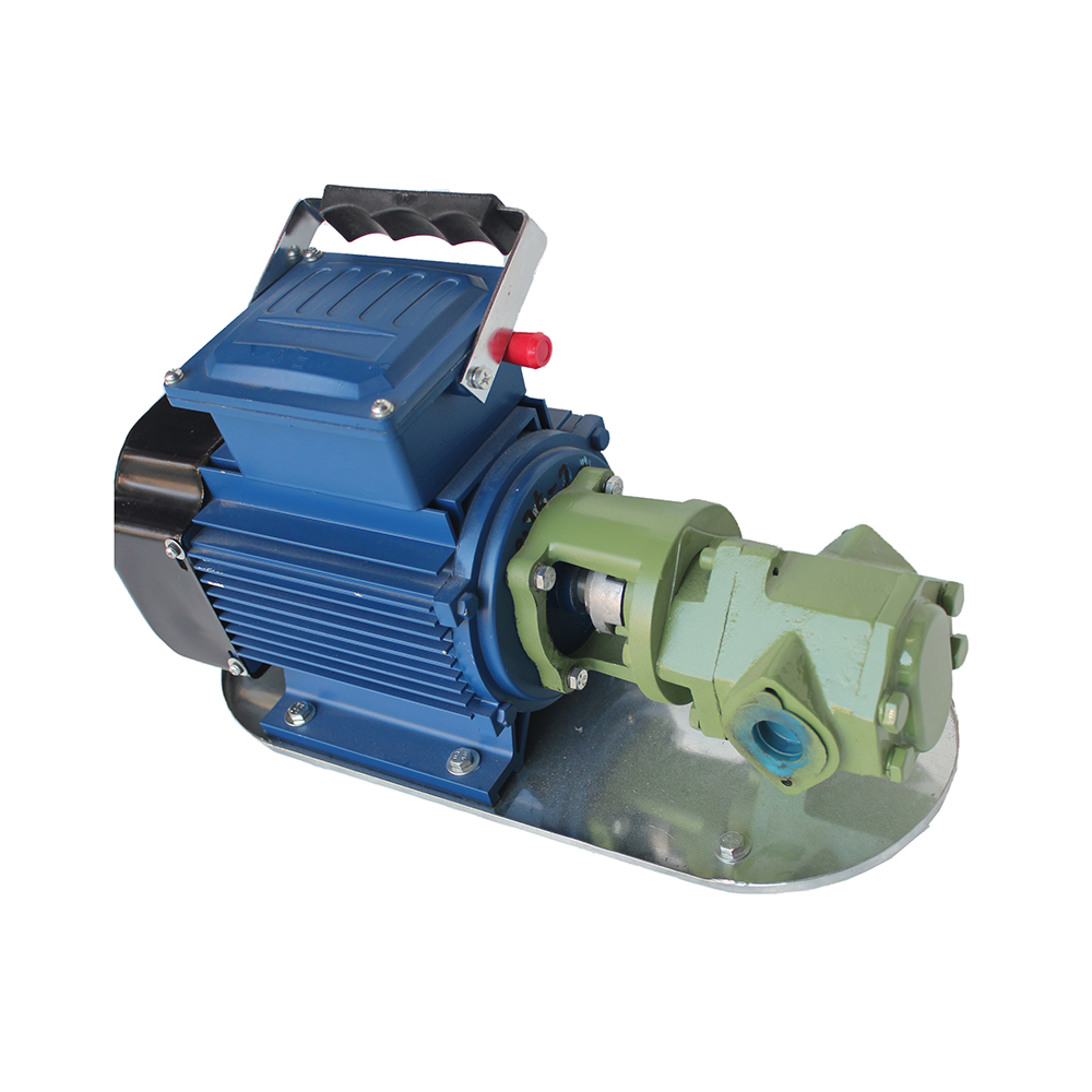
A gear pump is a positive displacement pump that moves fluid by using rotating gears to trap liquid in cavities between the gear teeth
and the pump housing, then transport it from the inlet side to the outlet side. Gear pumps are widely used because they offer
consistent flow, compact structure, simple operation, and reliable performance in demanding environments.
In industrial applications, gear pumps are commonly selected for fluids with moderate to high viscosity, including oils, lubricants,
fuel, resins, additives, and other process liquids. Their performance depends heavily on correct installation, secure mounting,
shaft alignment, suitable piping, proper priming, and system cleanliness.
Why Gear Pump Installation and Alignment Matter
Installation and alignment are not minor setup tasks. They are core performance factors that influence pump efficiency and reliability.
Even a high-quality gear pump can experience premature failure if the base is unstable, the shaft is misaligned, the piping loads the casing,
or the system is not prepared correctly before startup.
- Reduces vibration and operational noise
- Extends bearing, seal, and gear life
- Improves volumetric efficiency and flow stability
- Minimizes heat generation and internal wear
- Lowers the risk of leakage and cavitation
- Supports safer and more predictable operation
For this reason, best practices for gear pump installation should be treated as part of the pump’s lifecycle strategy rather than a simple
commissioning step.
Key Benefits of Correct Gear Pump Alignment
Benefit |
Description |
Operational Impact |
|---|
Reduced wear |
Proper alignment lowers stress on shafts, couplings, bearings, and seals. |
Longer service life and fewer repairs. |
Lower vibration |
Aligned systems operate more smoothly with less mechanical oscillation. |
Better stability and reduced noise. |
Higher efficiency |
Reduced friction and load losses improve pump performance. |
Better output with less energy waste. |
Improved sealing |
Correct shaft positioning helps seals operate within design limits. |
Reduced leakage risk. |
Fewer shutdowns |
Reliable alignment prevents frequent failures and unplanned maintenance. |
Better uptime and productivity. |
Common Types of Gear Pumps
Understanding pump type is important before installation because internal structure, pressure handling, and alignment sensitivity may vary.
The most common types are external gear pumps and internal gear pumps.
Gear Pump Type |
Basic Definition |
Typical Use |
Installation Note |
|---|
External gear pump |
Uses two externally meshing gears to move fluid. |
Hydraulic systems, lubrication, fuel transfer. |
Requires precise shaft alignment and stable mounting. |
Internal gear pump |
Uses an internal and external gear with a crescent or similar separator. |
Viscous fluids, polymers, oils, chemical applications. |
Needs clean suction conditions and correct speed setup. |
Gear metering pump |
Provides accurate flow control for small or precise volumes. |
Metering, dosing, dispensing systems. |
Alignment and clean piping are critical for accuracy. |
Pre-Installation Checklist for Gear Pump Setup
Before installing a gear pump, the system should be inspected carefully. Pre-installation planning reduces errors, prevents contamination,
and ensures that the pump is suitable for the application.
- Confirm pump model, rotational direction, and operating range
- Check fluid compatibility with pump materials and seals
- Verify inlet and outlet sizing
- Inspect foundation, baseplate, and mounting surfaces
- Review coupling type and shaft connection method
- Ensure suction piping is short, straight, and properly sized
- Prepare filtration and contamination control measures
- Confirm lubrication requirements for bearings and seals
- Check motor or driver specification and speed rating
- Review start-up and shutdown procedures
A careful gear pump installation checklist helps avoid common commissioning problems such as dry running, cavitation, reverse rotation,
and mechanical overload.
Best Practices for Gear Pump Installation
The following installation practices are widely recommended in industrial pumping systems. They apply to most gear pump configurations,
though exact requirements should always match the pump’s technical documentation and application conditions.
1. Install on a stable and rigid base
The pump and driver should be mounted on a solid foundation or rigid baseplate. Any flexing, twisting, or uneven support can create
misalignment and vibration. A stable base improves long-term reliability and helps maintain alignment under operating load.
2. Use correct coupling alignment
Shaft and coupling alignment is one of the most important installation steps. Misalignment can be angular, parallel, or combined.
Even small deviations may increase load on bearings and seals. Alignment should be checked during installation and again after the system
reaches operating temperature.
3. Keep suction piping short and unobstructed
Gear pumps perform best when inlet flow conditions are smooth and unrestricted. The suction line should be as short and straight as possible,
with minimal elbows, valves, or sudden diameter changes. Excessive suction resistance can lead to cavitation, reduced performance,
and noisy operation.
4. Avoid piping stress on the pump casing
Piping should be independently supported and should not pull, push, or torque the pump body. External pipe loads can distort the casing
and disturb internal clearances. Proper pipe support is a major part of best practices for gear pump installation and alignment.
5. Verify rotational direction before startup
Gear pumps are direction-sensitive. Running the pump in the wrong direction can reduce or stop flow, damage internal components,
or create abnormal pressure conditions. Always verify arrow markings, driver wiring, and rotation checks before the first startup.
6. Prime the pump if required
Some gear pumps are self-priming under specific conditions, but many systems still benefit from proper priming. The pump chamber and suction line
should contain fluid before full-speed operation to reduce dry running and startup wear.
7. Install proper filtration
Clean fluid is essential for gear pump performance. Particles can damage gears, bearings, and seals. Filtration should be selected according
to the system’s cleanliness target and fluid characteristics. Cleanliness is especially important in hydraulic and precision metering systems.
8. Provide pressure relief protection
As positive displacement pumps, gear pumps can generate high pressure if discharge flow is blocked. A correctly sized pressure relief valve
or system safety device is often necessary to protect the pump and connected equipment.
9. Check seal and lubricant compatibility
Mechanical seals, lip seals, O-rings, and bearing lubrication must match the fluid type, temperature, and pressure. Incorrect material selection
can cause leakage, swelling, hardening, or premature failure.
10. Perform staged startup
Startup should be gradual. The system should be monitored for noise, vibration, pressure rise, leakage, and temperature. If abnormal conditions
appear, the pump should be stopped and inspected before continuing operation.
Gear Pump Alignment Methods
There are several common methods for alignment depending on accuracy requirements and available tools. The objective is to ensure the pump shaft
and driver shaft operate on a compatible centerline with minimal strain.
Alignment Method |
How It Works |
Typical Use |
Advantages |
|---|
Straightedge and feeler gauge |
Manual method using visual and gap measurements. |
Basic checks, small systems. |
Simple, low cost, quick for preliminary alignment. |
Dial indicator alignment |
Measures shaft or coupling movement with precision indicators. |
General industrial alignment. |
More accurate than basic manual methods. |
Laser alignment |
Uses optical sensors to measure shaft position and angle. |
High-precision and critical applications. |
Fast, highly accurate, repeatable. |
Soft foot correction |
Identifies uneven support under machine feet before alignment. |
All rotating equipment setups. |
Prevents distortion and false alignment readings. |
Step-by-Step Alignment Process
- Inspect the base and feet: Ensure the pump and motor sit evenly without rocking or distortion.
- Correct soft foot: Add shims or adjust supports so all feet are stable and seated.
- Rough align the shafts: Position the driver and pump close to centerline before fine adjustment.
- Measure alignment: Use a dial indicator, laser tool, or approved method to check angular and parallel offsets.
- Adjust shims and position: Make controlled corrections to reduce misalignment within acceptable limits.
- Recheck after tightening: Bolts can change position during tightening, so readings should be confirmed again.
- Verify coupling clearance: Ensure the coupling is installed according to specification and not under stress.
- Perform hot alignment check: If required, recheck after thermal stabilization because heat can change shaft position.
Typical Gear Pump Technical Specifications
Technical specifications vary widely by design and application. The table below shows general industry reference values for informational use.
Actual values must always be confirmed for the selected pump model and service conditions.
Specification |
Typical Range |
Notes |
|---|
Flow rate |
0.1 to 500+ GPM |
Depends on displacement, speed, and fluid viscosity. |
Operating pressure |
50 to 3,000 PSI |
Application and construction determine pressure capability. |
Speed range |
100 to 3,600 RPM |
Higher speed may increase wear and noise if not properly controlled. |
Viscosity range |
Low to very high viscosity |
Gear pumps are often preferred for thicker fluids. |
Temperature range |
Depends on materials and fluid |
Seal and bearing selection affect thermal performance. |
Mounting style |
Base-mounted, flange-mounted, bracket-mounted |
Must match driver and system layout. |
Connection types |
Threaded, flanged, sanitary, or custom |
Should support clean, secure flow connections. |
Recommended Installation Clearances and Alignment Tolerances
Exact tolerances depend on pump size, coupling type, speed, and manufacturer guidelines. The values below are general reference ranges
for industrial alignment planning.
Parameter |
General Reference Range |
Purpose |
|---|
Parallel misalignment |
Typically kept to a very small fraction of an inch or within microns |
Protects bearings and couplings from side loading. |
Angular misalignment |
Minimized to near-zero at the coupling |
Ensures smooth torque transmission. |
Base flatness |
As even as practical across all mounting points |
Prevents soft foot and frame distortion. |
Suction lift |
As low as possible |
Reduces cavitation and inlet restriction risk. |
Pipe strain |
Should be effectively zero at the casing |
Prevents mechanical stress and seal damage. |
Common Mistakes During Gear Pump Installation
Many gear pump problems begin during installation rather than during operation. Avoiding the mistakes below can significantly improve
performance and reduce downtime.
- Ignoring baseplate leveling and soft foot correction
- Connecting piping that places load on the pump housing
- Skipping alignment checks after tightening bolts
- Starting the pump dry or partially primed
- Using oversized or undersized suction piping
- Failing to confirm rotation direction
- Allowing contamination to enter the system
- Neglecting pressure relief protection
- Installing incorrect seal materials
- Running the pump at speed beyond its design range
Symptoms of Poor Alignment or Improper Installation
If a gear pump is installed incorrectly, the system often shows warning signs early. Recognizing these symptoms helps prevent major damage.
Symptom |
Possible Cause |
Recommended Action |
|---|
Excessive vibration |
Misalignment, loose mounting, pipe strain, imbalance |
Inspect foundation, coupling, and piping support. |
High noise level |
Cavitation, dry running, internal wear, suction restriction |
Check inlet conditions and fluid supply. |
Reduced flow |
Incorrect rotation, wear, leakage, blockage |
Verify direction and system restriction. |
Seal leakage |
Misalignment, pressure spikes, incompatible seal material |
Review alignment and seal selection. |
Overheating |
Friction, overpressure, poor lubrication, internal recirculation |
Inspect operating conditions and clearances. |
Frequent bearing failure |
Shaft loading, vibration, contamination, poor installation |
Check alignment and cleanliness. |
Gear Pump Installation and Alignment FAQ
How important is alignment for a gear pump?
Alignment is extremely important because even small errors can increase wear, reduce efficiency, and shorten service life. Correct alignment
helps the pump and driver operate smoothly and safely.
Can a gear pump run if the coupling is slightly off?
It may run, but long-term operation with misalignment is not recommended. Even minor offset can create vibration, heat, and premature damage.
What causes gear pump cavitation?
Cavitation is commonly caused by inlet restriction, insufficient suction pressure, high fluid viscosity, air ingress, or excessive speed.
Proper piping and installation help prevent it.
Should the suction line be larger than the discharge line?
In many applications, the suction line is designed to reduce pressure drop and support inlet flow. Exact sizing depends on fluid properties,
system design, and pump requirements.
Is laser alignment necessary?
Laser alignment is not always mandatory, but it is a highly effective method for achieving precision. It is especially valuable in critical
equipment setups and maintenance programs.
SEO Keywords for Gear Pump Installation and Alignment Content
To support search visibility, this topic naturally includes relevant keywords such as:
gear pump installation, gear pump alignment, gear pump mounting, gear pump setup, pump shaft alignment, hydraulic gear pump installation,
industrial gear pump alignment, pump baseplate installation, suction piping best practices, positive displacement pump installation,
gear pump startup procedure, pump vibration prevention, and pump maintenance best practices.
Using these terms in headings, body text, FAQs, tables, and supporting descriptions helps improve topical relevance for search engines while
keeping the page useful for readers and engineers.
Conclusion
Best practices for gear pump installation and alignment are fundamental to achieving consistent pump performance, long equipment life,
and efficient operation. A properly installed gear pump is less likely to experience vibration, leakage, overheating, cavitation, or early wear.
By focusing on stable mounting, accurate shaft alignment, clean piping, correct rotation, proper priming, and careful startup procedures,
industrial users can significantly improve reliability and reduce maintenance costs.
Whether the application involves hydraulic power, lubrication, fuel transfer, or viscous fluid handling, the same principle applies:
successful gear pump operation begins with correct installation and alignment.
```

 Pусский
 ???????
 中文
中文







 Phone
Phone
Comment
(0)